Category Archives: Marklin Z Repair Notes

New Marklin Z Loco Design and Groovy Train Set

Marklin 81356 (photo courtesy Marklin)

Marklin’s MHI Release 81356 includes a new design Class 141 electric locomotive and 3 “Silver Coin” coaches comprising their “Commuter Service” train set, but first let’s look at the loco’s new design.

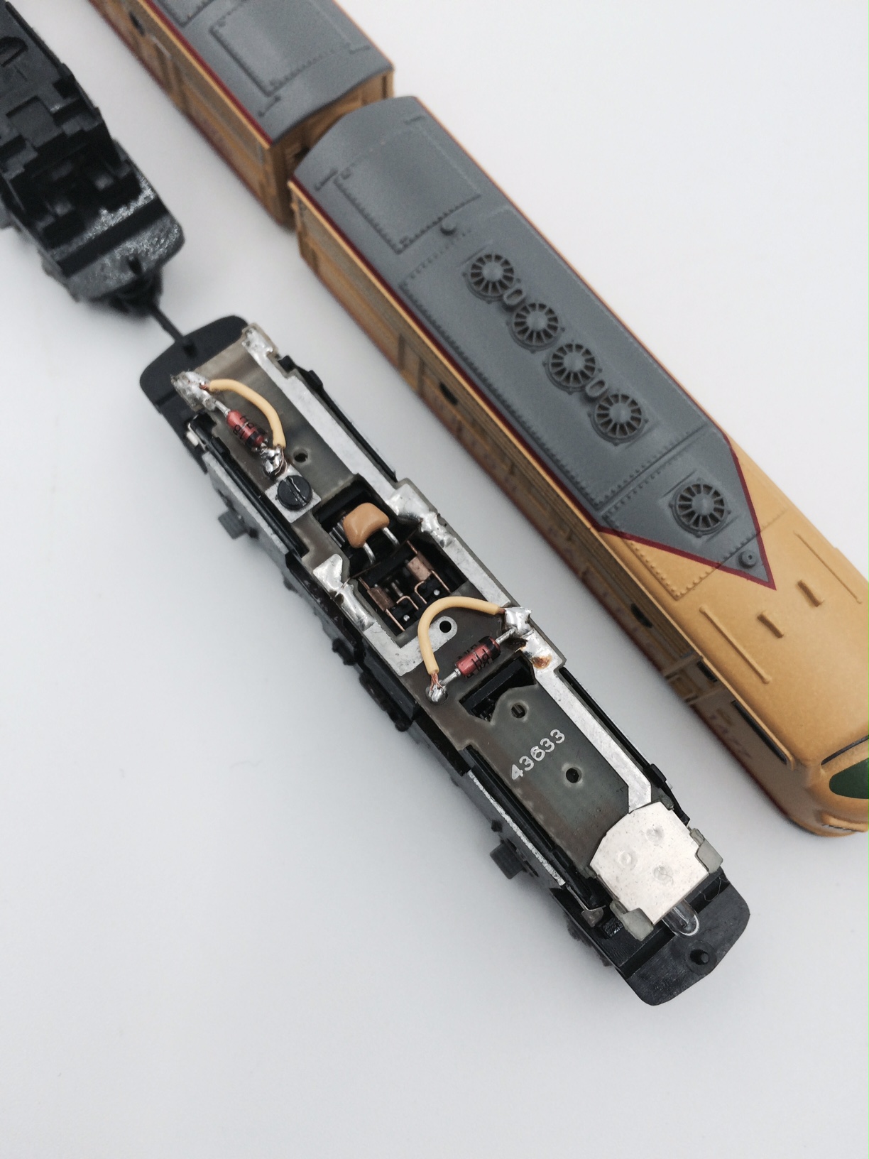
Under the shell are numerous new details at work to support the new motor concept currently being used in new locos. A few basic observations are the robust cast metal frame supporting the circuit board and trucks. Another interesting detail about the frame is its split design: frame is actually two parts held together with 6 machine screws located variously: 1 pair each end and 1 pair in the middle inside an easily removable section between the trucks. Circuit board is sandwiched between the two sections of frame as are all inner workings, and lamp circuit boards are held in slots front and back, two small pieces of black foam are installed between the two sections of frame below the lamp circuit boards. Everything looks different than a traditional Marklin Mini-Club model, but similar in their straight forward design thus it is possible to take it apart but with some difficulty.

Removal of 6 screws holding the frame together should provide easy disassembly of the loco but that is not the case. Bushings holding the frame parts and screws are tightly fitted and prone to breaking plus circuit board is taped down on one end (2 bushings on my loco were stripped with a crack in one). And freeing the circuit board is half the battle as the frame is gently pried apart a little at a time from end to end with care not to break the bushings. Bushings are tightly mounted in the frame thus the frame is tightly held together even without the screws, it appears the screws main job is expanding the bushings thus making a tighter connection with the the 2 part frame (?).

After the frame is pulled apart the trucks simply pop out, their plastic housings fit within indents in frame and secured by pressing the frame parts together. A further interesting detail about the trucks are the nylon gearing which have been greased not oiled at the factory. And coupler/spring assembly is secured by plate facing up rather than down as with previous locos. If there is a problem with coupler/spring which there shouldn’t be the loco will have to be taken apart to free the trucks.

A motor with robust worm drive is maintenance free (no brushes to be replaced) and quiet to run, but instructions do advise oiling the trucks from time to time (intervals of 20 hours run time). Note: small pieces of yellow acetate are mounted below both lamp circuit boards.

The loco in my set arrived with poor/non-working running characteristics, one truck stiff and seized (angled upward not parrellel to underside of shell): trucks should rock gently up and down with wheel-sets able to make contact with track. Taking the loco apart and reassembled fixed the problem: something was out of sync likely due to shipping. Not a big deal, but I would advise sending defective items back to Marklin thus receiving full warranty coverage, I don’t advise following my lead.

The shell of this loco is a real winner as can be seen on the roof with improved detailing with addition of add-on parts. And grab rails below windows on both ends. The latter was a great surprise! This set is part of a small handful of items in recent years manufactured in China following the Kittel of recent memory.

Marklin’s description of the set: German Federal Railroad (DB) “Commuter Service” train set: 1- class 141 electric locomotive with 5-light headlights / marker lights, multiple forced air vents with vertical fins, and a continuous rain gutter, 1- type Bnrzb 725 “Silberling” (Silver Coins) commuter car, 2nd class, 1- type ABnrzb 704 “Silberling” (Silver Coins) commuter car, 1st/2nd class, and 1- “Silberling” (Silver Coins) commuter cab control car, 2nd class, with an engineer’s cab. All of the units look as they did in Era IV. Special One Time Release for the MHI Program (Marklin Handler Initiative).

81356-1 (Class 141 electric locomotive)
81356-2
81356-3 (Note: yellow stripe denotes 1st class section)
81356-4 (note: headlamps, marker lights and destination board illuminate in both directions of travel

Siding: Parts List for this set does not include part numbers for retaining bushings for frame and no part number for circuit board, Marklin indicates parts on schematic without part numbers require Marklin repair department.

Royal Wurttemberg (K.W.St.E) T 9 tank locomotive: Marklin 88952

The 2005 release of the Marklin T 9 tank locomotive painted and lettered for the Royal Wurttemberg State Railroad (K.W.St.E) featured a 5 pole motor and it was the first of its type for this railway produced in the mini-club line-up.

The 88952 produced in 2005 as a “one time series” celebrated “200 Years of the Kingdom of Wurttemberg.”

The Era I locomotive is appropriately coupled with Wurttemberg coaches: 80105, 8700, 8701, and 8739. Marklin’s recent release 5 coach set is also a very good choice: 87009.

Coach 8739 trails the T 9 with destination boards for Boll-Goppingen, its operating number E4 2733 was produced by Marklin from 1989-1998. Eleven years in production does not make this coach particularly rare, but this open corridor coach has been popular with modelers of early trains. Check out the next section detailing the relationship between this coach and locomotive.

Following years of innovation by modelers of Z one such development proved invaluable: marrying coaches with short locomotives. Locomotives of short length and weight have proven to be less than rewarding to operate on the mini-club layouts with turnouts and crossovers with their slight dip in power, short locos are challenged to pass freely through these track features, but one creative minded individual came up with a solution: wiring the axles of a coach to the leads of the locomotive thereby extending the length of the locomotive. In this case the 88952 with 3 powered axles has been extended with 2 additional axles. Wiring the coach involves some soldering and drilling with micro bits, but it is overall a fairly straightforward and easy repair the second time around, the first time should be counted as a learning curve. Adding an LED light panel at the same time is just a little more work. In this example a draw-bar was installed thus permanently coupling the loco and coach together. Performance for this type of locomotive is improved greatly.

Here are photos of the electrical upgrade:


UP + SP E8’s: joint collaboration Marklin/AZL

Marklin 88627
Marklin 88626 (only 46 prototypes were produced of the E8 ‘B’ unit)
Marklin 88628

The post war General Motors E8 diesel locomotive was built by their Electro Motive Division (EMD) in Illinois, it boasted a power reserve of 2250 hp for passenger service. Some units remained in service into the late 70’s pulling freight trains. Significantly longer than the F7 with significantly fewer produced than the latter, the E8 was designed with 2 – 6 axle trucks with 450 ‘A’ units produced versus more than 2000 F7 ‘A’ units.

Several prototypes were modeled in Z for the PRR, UP and SP railroads as a joint venture between Marklin and AZL, but aside from Marklin trucks/couplers and box the collaboration seems limited in scope with majority partnering coming from AZL.

Crisp graphics and accurate paint schemes plus detailed shells and trucks are equaled by what’s inside: heavy ballasting and robust brush-less motor.

Taking a look inside these locomotives reveal several unique design features of AZL versus Marklin including a heavily ballasted two-part frame. Holding the frame together are 3 pairs of phillips head screws which all but conceals the motor and transmission except for the circuit board which rests on top.

partial disassembly of E8 ‘A’ unit with showing skirting replacement part and extra truck included with loco

Servicing either of the trucks requires popping off the fuel tank thus revealing the middle set of screws: loosen only. Service one truck at a time by removing its designated pair of screws followed by gently prying the frame apart thereby allowing the truck to pop out. Repeat for other truck and test on track before reattaching fuel tank cover and shell.

one end of frame slightly pried apart allowing removal of truck, worm gear and pick-ups run length of frame
fuel tank and truck removed from frame, truck is held in frame within the recess in frame’s casting, two sides of frame secured with screws closes the space around top of truck frame thus securing in place
1 traction tire per truck and 2 powered axles per truck
locomotives come with Marklin couplers installed which can be replaced with provided skirting, also included is an extra truck, photo shows location of 3 screws per each side of frame
circuit board and LED light panel at one end are visible without shell, photo shows correct gap between two frame sides, drive mechanism is held within frame

Note: AZL gearing is comprised of nylon gears versus Marklin machined metal gearing, and AZL factory lubrication is grease versus oil.

brass worm gear and plastic skirting mount at frame end, frame is pried apart to allow truck removal

A full disassembly of the chassis and motor entails removing all 6 screws that hold the frame together with all components smartly fitted within. It should be noted that proper assembly of the frame leaves a consistent gap between the two sides: two frame sides do not touch. Transmission is properly fitted with plastic intermediary part positioned with prong ends down and engaged with holes in frame. Parts comprising motor and transmission must be seated properly for reassembly of frame, it is very important not to force these parts together.

truck gearing is permanently installed versus the take apart nature of Marklin trucks
inside and outside view of frame sides: worm gears held in place with nylon guides seated prong side down in designated holes
Inside view of the frame sides reveals a straightforward design concept
underside of frame shows normal gap between frame sides

The 3 ‘A’ units come equipped with prototypical skirting to replace the Marklin coupler which is simply installed following removal of shell, un-clipping coupler and spring, and sliding new skirting part with prong ends into frame recepticle.

LED light panel sits in slot with skirting bracket held in place with pressure from frame sides
skirting bracket is a two outlet plug which accepts the 2 prongs from the replacement skirting part, coupler is held in place with a removable metal clip otherwise the coupler includes the Marklin style coupler and spring, LED light panel is seen at the top of the frame assembly held in place with a designated slot
unique removable metal clip system for the coupler otherwise a normal Marklin set-up

Pulling power is further improved with traction tires which in combination with the heavy cast metal frame evenly distributed across the wheels ensure smooth operation. No need at all for adding extra weight to these locos!

Roof equipment varies between the prototypes thus the models reflect prototypical accuracy.

roof equipment varies between the locomotives

Very impressive locomotives from the stand point of aesthetics and performance unfortunately the installed Marklin couplers do not allow use of the only appropriate coaches produced by AZL. Maybe coaches are in development?

Siding: Marklin 88629 (PRR) is the fourth locomotive in this series


Marklin F7 A-B-A sets: improving performance

If you are lucky enough to own one of the Marklin F7 sets “Alaska” or “UP” consider this easy repair. Or if you don’t like the wires running through the locos consider this easy repair.

Removing the wires is step 1: cut the wires before removing the shells and carefully remove the wires leading to each circuit board.

Soldering in place four very short wires is step 2: cut 4 small wires to bypass the 4 diodes on both circuit boards and carefully solder the wires in place.

Result: no wires running through the A-B-A units and much improved running performance thus allowing each locomotive to work independently of each other. Note: headlamps will light in both A units at the same time.

Marklin 89982: Turntable with accessories

A number of options exist for buying a Marklin Turntable beyond new and used with dealers offering new old dealer stock of the original turntable alongside the current offerings by Marklin. A release from 2014 included the turntable with accessories as item number 89982, this included 2- three stall loco sheds based on the “New Objectivity” architectural movement and a railway administration building.

Marklin has discontinued the 89982, they are now offering the turntable with controller and transformer only as item #89983, the loco shed building kit is also available as an accessory with item #89835. What is currently not available is the build kit for the railway administration building which is a wonderful example of the Bauhaus architectural style of the early 20th century and is fully complemented by the same era roundhouse. The railway administration building was reason enough for me to buy 89982 which is as beautiful in person as the Marklin promotional photos.

The Railway Administration Building features 2 partition walls, numerous windows and flat roof, its measurements: 7 1/2 inches (length) x 1 3/4 inches (depth) x 1 11/16 inches (height).

Building the kit is easy and straightforward with no issues.

Six stall roundhouse features steel framework and brick infill, it is a very attractive building with rather plain doors that do not swing open and closed with the precision of the Archistories Roundhouse ARC-112121 and accessory Stalls ARC-113121. Interior supports are a bit flimsy and easily bend out of shape, but overall a very good kit that I recommend.

The kit can be built as two separate buildings with 3 stalls each or as one 6 stall roundhouse in which case two exterior walls are omitted, I opted for two buildings.

Unlike the Archistories loco sheds which incorporate 2 part window and door framing with snap in place glazing this kit requires gluing glazing to the interior side of the door. To compensate for the plain doors I decided to age them. First I used a light wash of grimy black (water-based) paint on the interior side of the glazing followed by dry brushing grimy black to doors and brick work around doors, I further lightly aged the bricks along the ground level around the perimeter of the buildings. Light and heavier pressure was used to vary the amount of color to the doors and bricks using dry brush with very diluted paint. Doors readily absorb paint so test a small area first.

Siding: original 3 pole motor turntables can be upgraded to 5 pole with part number 211914.

Marklin 89941 Transfer Table: brief notes on history and repair

First introduced to the mini-club line-up in 1977 the 8994 transfer table would remain unchanged in design until 2002 when it was upgraded with a 5 pole motor and the item number was extended by a ‘1’. From 2003 until 2012 the 89941 transfer table was available with a few packaging changes including white versus blue transformer and controller plus a five pole motor. Manufactured throughout its long history in Italy the transfer table is a very well designed and precision accessory for mini-club, it could be used on a layout for modeling steam and diesel, but it could also be accessorized with catenary for electric locos.

I have seen many early and late transfer tables and all were in excellent working condition owing to the excellent design and manufacturing.

The one and only issue with the transfer table 89941 that is easily overcome has to do with delivery specs, three times 89941 was delivered to a local dealer from Walthers and each was afflicted with the same issue: motor housing top plate separation and subsequently gearing detached along with operators’ cabin. No fear, I was able to easily put each back together again. Probably poor packing and shipping from Walthers to Pennsylvania shook things up a bit, but the problem was easily mitigated, and I wanted to share brief notes on the motor housing for new and old transfer table fixes, repairs and restorations.

The motor housing on the transfer table is easily accessed by slipping off the operators’ cabin and then gently working off the top plate of the motor housing which is held in place by clips. Inside the motor housing three sets of gears and the motor. If you need to remove hardened oil simply remove the vertical gear and top gearing to connects with motor and soak in original (blue) Windex, leave motor and second gear in place and with careful use of toothpick, tweezers and very small cleaning cloth remove dirt and hardened oil from the inside of motor housing. Don’t obsess here, normal loco dirt and debris such hair do not afflict this part, careful not to add lint to the housing by cleaning.

To reassemble the motor housing locate mounting hole for vertical gear in base of motor housing (see shiny brass part with hole in base), worm drive end of gear sits in this hole. Note: worm gears align with regular gears only, they do not function together. Large gear is correctly installed on top engaged with worm gear (bushing on each end of top gear that engages with motor allow it to move freely, double check this gear is properly installed before proceeding). Before attaching top plate locate hole with brass bushing, this hole will align with top of vertical gear. Lastly slide on top plate and test.

Underside of top plate with brass bushing, top of vertical gear sits within the bushing.

Everything fits correctly when the motor housing has no gaps.

Note: bridge only moves with power applied when gearing is properly installed, it will not move freely unless the vertical gear is removed from the motor housing.

Don’t be afraid to buy the transfer table used, I have never seen one that can’t be restored with a simple cleaning or realignment of the bridge and those include some late 1970’s examples.

Good luck and happy railroading. Stay tuned for the next post, an exciting loco shed to go with the transfer table has just been released!

Archistories ARC-104171:

Siding: realistic modeling might include weathering of the bridge and attaching corrugated steel in the form of laser cut cardstock to the roof of the operators’ cabin.

Engineering Perfection: Marklin E 18 in ‘Z’!

I recently purchased a rare variant of the E 18 electric locomotive in Z by Marklin, it arrived as a used working model, but with a fair amount of dirt and hairs strangling the axles. Cleaning it up included taking it apart and removing the dirt and grime under the hood, but it also included removing excess oil that even found its way under the circuit board. No HOS (hardened oil syndrome) to deal with, but over oiling has its issues including attracting dust and damaging the motor, in this case not much damage occurred to the locomotive.

This post is not so much inspired by the normal reporting of mini-club locomotive maintenance instead it is one that was inspired by the brilliant engineering and design of the E 18 for mini-club.

Marklin does not apply the same rules and principles when designing a mini-club loco: same motor and chassis different shell, no Marklin designs each locomotive class from the ground up thereby insuring the prototype is accurate in 1:220 scale and operates as flawlessly as we have all come to expect from mini-club operation!

Marklin 88082: rarest E 18 variant from 2004

The E 18 is an example of one such mini-club locomotive design that incorporates unique engineering and casting that is also meant to be taken apart and repaired when the need arises.

Taken apart this locomotive has a lot of parts that work flawlessly in the assembled locomotive including two gears that sit on posts within the frame and two large gears allowed to float on their axles.

above photo: right- small metal gear sits on post within frame as well as a second one not pictured, 2 additional gears one synthetic with two sets of gearing sit posts that are inserted through frame body

above photo: left- drive wheels that float on their axles pictured left are assembled in slots on the motor end of frame, two drive wheels right use thinner gears that are permanently fixed in the center of axles which are thicker than floating axles.

The design concept is simple: gather electricity from the wheels by way of a circuit board, the turning worm gear (transmission) on the motor engages with gearing that engages all the way down to the wheels thereby making all wheels drive wheels except for the pilot wheels.

Note: plastic mini-club loco shells are removed without damage with super thin synthetic guitar picks, do not use metal screwdrivers famously illustrated in the Marklin instruction manuals boxed with the locomotives.

With the shell off the cast wheel details are carefully pulled off, they are simply held onto the frame with posts!

Circuit board is not held under clips as with other locomotives, and one screw is all that is required to hold it in place.

The motor is screwed to the frame with 2 brackets each installed with two screws. Note: if you are at this point in restoration it is advisable to remove the motor and clean the frame under it. It is also a good idea to test the motor out of the frame, inspecting the brushes is also a good idea at this point.

After cleaning all the gears replace in the frame with the two gears on posts first followed by the large gears (2 gears that are designed to float on their axles are installed on the motor side of the frame, thickness of these axles also match the machining on the frame).

Note: use care to prevent bending of the copper leads on sides of frame.

Final steps: clipping on the wheel detail sections and then shell: Voila!!!!!

Variants of the German E 18 in mini-club:

Marklin class E 18 for DB (88080) Era III:

Marklin class 118 for DB (88081) Era IV:

Marklin class 1018 for OBB (88082) Era IV:

Marklin class E 18 42 for OBB (81441: trainset with coaches) Era III:

Siding: no other Z scale loco is designed to be taken fully apart and easily assembled as mini-club: diesel and electrics are easier than steam and non articulated are easier than articulated.

Siding: all class E 18’s are sold out at the factory, but Walthers still has the 81441 trainset available with beautiful green livery and 4 skirted coaches.


Marklin’s New Brushless Motor: Good News Follow-up!!!!!!!!!!!!!!!

The other day I submitted a post for your review which posed questions about the new brushless motors making their appearance in Marklin Z locos. And one example of a new release steam loco that had an operating issue that I included in that review.

The steam loco is the Bavarian 88923 with the very detailed running gear and side rods, out of the box it inexplicably stopped in the forward direction but ran well in reverse. Today I decided to problem solve the running performance and discovered some interesting things about the new motor.

Note: roller stands are great on those occasions a loco needs testing, they keep it in place so inspecting what is wrong is easy. Many companies make roller stands, this one is by Marklin (89932).

The new motor for the 88923 is a solid case brushless type that attaches to the end of the loco chassis in much the same way as the former 3 and 5 pole mini-club brush motors: a permanent gear mounted to the motor engages with the transmission gear whose other end is the worm gear which engages with the gears that move the wheels. The motor is secured to the chassis with a single screw like before, but the new motor has two alignment pins that engage in the end of the chassis which place the motor and chassis in precise alignment. Out of the box this loco ran rough in forward and stopped, but it ran well in reverse. I took the loco apart and removed the motor and transmission gear, I carefully reinstalled the transmission gear after applying a drop of oil on the worm gear and opposing gear, I was careful to align the two pins on motor with chassis applying a little pressure. It took 4-5 tries after moving the gears a little bit to properly seat the chassis and motor, but the tolerances seem to me to be more stringent with this new motor. The old motor assembly of the brush motors seem to have a little wriggle of the shaft and transmission gear alignment which suited that design well, but I believe the new motor assembly is a tighter system at this connecting point between motor/transmission gear/chassis. The glitch I experienced I believe was a very slight misalignment during assembly. I am happy to report that the loco runs like a dream, it is quiet and runs at very low speeds.

Photos: under the hood of the 88923 shows wire leads from motor soldered to chassis pick-ups which are taped down to facilitate removal and installation of shell. Note: solid motor case with no access points for oiling, this is a maintenance free system. Normal sparse oiling of wheel-sets still applies. Hiding wires will be part of this new world of mini-club, but this example has deep channels on each side to hold the wires flush and out of sight.

The new loco for Kay.Bay.Sts.B is not only a great runner, it is a wonder to watch the lively action of the side rods. The shell detailing and paint scheme complete this work of art, it is spectacular!!!!

Note: instructions that were packed with my loco show it with the old 5 pole E251 202. The installation of the new motor in this loco may not have been originally planned, but you will know which motor you have in this loco by looking at it: solid case is that of the new brushless motor original 3 and 5 pole motors had a center bushing that required a very lite drip of oil periodically.

Link: original instructions for the 88923 showing 5 pole brush motor thus incorrect oiling instructions are outlined

https://static.maerklin.de/damcontent/8e/b3/8eb3f2fa2c6e805cc71c54ea3801462c1489755052.pdf

Photo: view of two Bavarian class S 3/6’s with new brushless motor (bottom: 88923) and former brush motor type (top: 8108)

Siding: motor upgrades have been available for all the mini-club locos since the 5 pole was introduced on the BR 143 in 1998 with some requiring soldering, I don’t think future upgrades with the brushless motor will be available to convert this locomotive class in former releases due to the machining of the frame with the 2 motor alignment holes.

Repainting 8135 coaches for the SJ: Part 3

This is the 3rd and final post on the repainting and lettering of the Marklin Dompfeil train set (8135) for the SJ.

Before (Marklin 8135):

After (SJ coaches using FR decal set):

At the start of this project I had never repainted a train car before or operated an airbrush thus much was learned.

SJ coaches in z scale have been extremely limited, FR released a type litt AB8k 1st and 2nd class in a single release of 30 only, FR 46.299.00 was based on a German built coach that was used on a ferry service. In order to accurately represent this coach FR modified a Marklin coach that was shortened by one window.

photo: FR 46.299.00 (edition: 30 total) – SJ type litt AB8k 1st and 2nd class coach

For those interested in SJ modeling in z there are numerous locos and freight cars by FR, but scant few passenger coaches until FR released a decal set several years ago intended for the Marklin 8135 coaches, these German built coaches for the Dompfeil train set were likewise used on the SJ.

The process of producing a set of 4 coaches started with disassembly of the coaches followed by stripping, in this post the final stages are documented including masking, painting, and lettering.

Identifying the sections to paint include the undercarriage, sides, and roof. The roof is a clip on part, it does not require masking unlike the shells. Painting two colors of the same part requires masking, I decided to start with the undercarriage and vestibules color, I sprayed the entire shells with this color with no masking.

Before applying the brown paint I masked off the vestibules and undercarriage. The masking material is similar to common masking tape, but it is markedly thinner with a slick surface, it also comes in a variety of widths. I chose masking tape of 6mm width manufactured by Tamiya.

After paint is dried the masking tape is removed, for areas not protected by masking retouching maybe required, I chose to paint the buffers with a brush as the final stage of painting, masking these seemed an impossible task and fine brush work produced great results.

The FR decals in the set are applied by rubbing onto the cars, they differ from other decals that are applied with water. The decals provided had alignment marks to make positioning easy, my burnishing tool was an artists’ burnishing bone, but a soft tipped lead pencil should work fine.

After decals are applied a final coat of clear lacquer is sprayed on to protect the finish and decals. And reassembly follows as the last step.

Notes on airbrushing: I purchased an Iwata Neo airbrush with an Iwata braided hose for just over $100. Several airbrush air compressors were available from the store I purchased the airbrush from with prices ranging in the $220-$300 range, I chose to use a Porter Cable pancake compressor I use for air tools. A fitting is available to connect the braided airbrush hose to this type of compressor for a few bucks. The only difference between an air tool compressor and a specialty airbrush compressor is one of noise, the airbrush compressor is very quiet while hearing protection is required with the pancake compressor. PSI (pressure per square inch) is a determined by testing on a piece of paper, I set the compressor gauge to 20 PSI which worked perfectly, others I researched recommend 15-20 PSI. Air brushes require cleaning after painting, cleaners are available or water can be used for acrylic paints. When the spray is clear the nozzle is clean, other parts should be cleaned as well. A cleaner between paint colors is also required.

Notes on paint: the consistency of paint should be the same as skim milk, most paints may require thinning with water to gain this consistency. I used Testors acrylic paints that I mixed to customize the color, they are railroad based colors that did not require any thinning. The clear coat I used is made by Iwata, it was the consistency of white glue and required thinning to spray. Acrylic paints dry quickly and can be layered on layer without skinning as can be the case with enamels or the combination of the two. The very best results will be achieved with 100% acrylic paints. Careful attention should be applied in mixing paints for airbrushing, straining maybe required to avoid clogs and poor paint results. For safety use a mask and gloves.

Notes on applying decals: as with much detail work careful consideration applies to attaching decals, they are transferred from a sheet to the model with burnishing tools. Best results are achieved with a level flat object, I use a specialty artists’ burnishing bone. Pointy tools will not work! Acrylic paints should be allowed to dry overnight to provide a hard surface for decal work. And very delicate handling until final spray coat of lacquer. I used clear lacquer with a satin finish which is consistent with Marklin’s coach finishes.

For close to two years I had the decal set and a second Marklin 8135 for this project, but I was reluctant to start due to lack of expertise. Plus I was apprehensive to strip the paint of mint Marklin coaches: after stripping there was no going back. I discovered that air brushing is easier than I thought producing a superior paint finish. Now I feel the airbrush is as important to the railroader as the soldering iron. Future uses for this new tool include weathering track, cars and locos.

Good luck and have fun!

Siding: FR’s Ra 987 electric locomotive is a compatible loco for this coach set, it is based on the prototype from the mid 1950’s:  FR 46.132.01 was produced in a limited series of 32 total, it is still available from quality-toys-trains on Ebay.


Rewiring Marklin 8871 and 88711: ICE trains go fast!

Marklin’s 1990’s releases of the TEE 8873 and ICE trains 8871 and 88711 suffer from a design flaw: poor electrical connections caused by the couplers and a train set wired in parallel. Similar to those old Christmas lights when one bulb went they all did, these Marklin train sets suffered a similar fate that was corrected with the further releases of the TEE variations. The ICE train sets changed in another way instead of having two powered units as did the 8871 and 88711 the 88712 and 88714 included one powered unit located in the middle of the train this being a coach.

A simple solution to to correct the poor performance of the three TEE and ICE trains is to bypass two diodes located on each circuit board of the powered units. There are four diodes located on each circuit board, two affect the lights (LED’s) and two are near the motor. Bypassing the diodes near the motor with a soldered wire is all that is needed to allow the locomotive to move forward and reverse thus allowing each powered unit to work without the former wiring constraints.

Note: no need to bypass the diodes on any other TEE train version released after 8873.

Note: 30 gauge wire is recommended for wiring circuit board, tinning the ends of wires is recommended before making the soldered connections.

The early ICE trains use an interesting light bulb with a red and a clear bulb soldered to a circuit board similar to the traditional mini-club bulb. The red bulb is hooded to direct the light better, but unlike the LED’s the light is rather dim unless the loco is cranking! Note: very fragile bulb and no longer available, but if you are good at soldering you can make your own.

The couplers as mentioned are faulty for electrical connectivity, but work great when both powered units are rewired: coach lights no longer flicker. The couplers for the two ICE trains are susceptible to damage due to the untethered ends of the copper strips, great care should be taken to prevent bending. A good recommendation is to stock up on parts as they become available on Ebay. The original couplers for the 8873 are infinitely more resilient than the couplers used on the first two ICE trains.

Note: save old loco light bulbs that don’t work, new ones can be easily made by using the original circuit board for soldering news bulbs to them, generic bulbs are available at train shops in the correct size.

Siding: the 5 pole motor replacement for the 8871 + 88711 is 211907 which is one of the more expensive motors for upgrade, and you will need two. I have not made the upgrade to 5 pole with my sets, the original 3 pole motors work exceptionally well at low speed and throughout the range, but the 5 pole motors would be much quieter.

Siding: removing the tight fitting shells from 8871 and 88711 is more easily accomplished with synthetic guitar picks of .70 mm thickness or thinner.